MXL V77 Mods
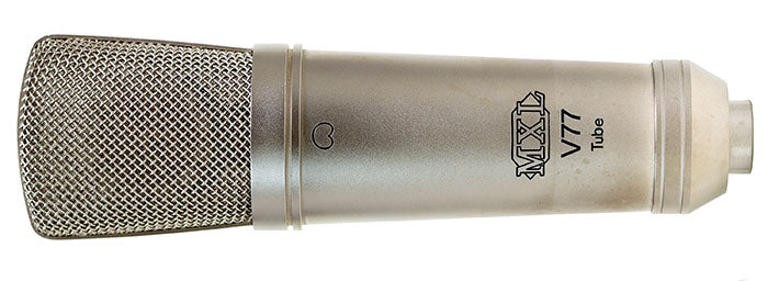
The MXL V77 / V77S Tube is an early tube mic, built for MXL by 797 Audio. Like many of the 797 products, the build quality is very good. Unlike many later-model MXL condensers, the V77 has a surprisingly neutral (unhyped) frequency response, at least in the sample mic we tested.
We do not make a circuit mod kit for this model, but we put together a list of upgrade possibilities.
Capsule Replacement
If your V77 needs a new capsule, we recommend the K67-S. The V77 circuit rolls off the top end by 2.5dB @ 10kHz, which provides sufficient corrective EQ for this K67 capsule.
Beware cheap K67 c(r)apsules from Ebay, Reverb, Ali Baba; many of these are very bright on top, and thin in the bass, resulting in a sharp and hyped sound even with in-circuit EQ.
Tube Replacement
The V77 we analysed had 25dB higher 3H distortion than a good tube mic (like our V-251 or 12-251) would. Replacing the tube with a selected 6072 should help. As of 2022, good vacuum tubes have become scarce and expensive. We might have some modern EHX 6072 available, and we might have some fully tested, microphone grade NOS 6072 available too.
Circuit upgrade ideas
Disclaimer: we have not tested any of these; proceed at your own risk. Make only one circuit change at a time, then test the mic to ensure that it still works properly.
- Make the capsule mounting post taller (or more literally put a 3D printed spacer or a stack of metal washers underneath it). This mic's grille is unusually tall, giving plenty of room to raise the capsule above the deck in order to minimize reflections. The post is already tall, but could be another 5-10mm taller without running the top of the capsule into the top of the grille.
- Replace C2 (output capacitor) with something nicer, ideally a film capacitor. It will see 175V during startup, although steady state voltage is closer to 115V. It would need to be rated for 250V. The stock mic has a 1µF electrolytic. It seems likely that the value could be smaller, 0.47µF or possibly 0.1µF, without losing bottom end. Using a smaller value allows you to use a higher quality capacitor there. Look for a high-quality metallized polypropylene cap.
- Replace C4 (cathode capacitor) with Nichicon UKA 47µF/16V. This cap only sees about 2V, so any 10V to 16V (or higher) electrolytic would work. (Small value UKA series caps are going out of production in 2022; try UKT if necessary.)
- Bypass C4 with a 0.1µF film capacitor. Installing a capacitor across C4's leads is impossible due to the tube location. Instead, strap the new capacitor (0.1µF/63V) across R7, which if the schematic is correct is parallel with C4. (It would be wise to verify that R7 is paralleled across C4 before installing the bypass cap there.)
- Replace C6 (input coupling cap) with 1000pF/100V polystyrene or a nicer box film cap. This cap shouldn't actually see any DC unless the capsule leaks, so a lower DC rating would probably be fine.
- For advanced modders: make a schematic of the B+ circuit in the power supply. Increase the value of the first two 22µF filter caps after the rectifier to reduce AC ripple and noise. Optionally bypass some of those larger electrolytics with 0.1µF/0.01µF film capacitors -- noting that they need a 250V minimum rating, and 400V would be preferred.