M-Audio Luna Mods
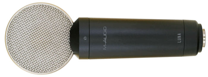 The M-Audio Luna is a large-diaphragm FET condenser with a transformer-coupled circuit. The circuit is a simplified version of what we first saw in the Groove Tubes GT55, although without a switchable pad or high-pass filter.
The mic has relatively high output, but relatively high noise, and a slightly over-bright voicing that limits the microphone's utility.
We have two modification options for the Luna microphone:
#1: Capsule Replacement
The capsule in the GT55 is K67 type, very similar to what you'd find in most of the large-diaphragm condensers made by MXL, Behringer, CAD, Apex, etc. This capsule suffers from a significant and harsh-sounding presence peak around 11kHz. Because the mic's circuit is linear, the Luna sounds too bright and hyped on many sources.
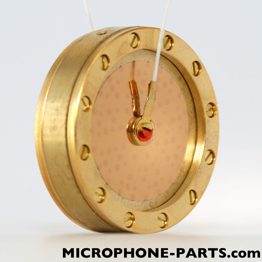 The RK-47 is a fine replacement/upgrade capsule. It is better suited to the stock circuit than is the Luna's original capsule, and it pairs beautifully with our T84-55 circuit also (see below).
The RK-12 is an alternative replacement/upgrade capsule for the Luna. It has a broader, lower amplitude presence boost in the high frequencies, giving the a much more balanced sound than does the original capsule. The RK-12 works equally well with our T84-55 circuit.
See below for specific capsule installation instructions for the Luna.
#2: Circuit Upgrade
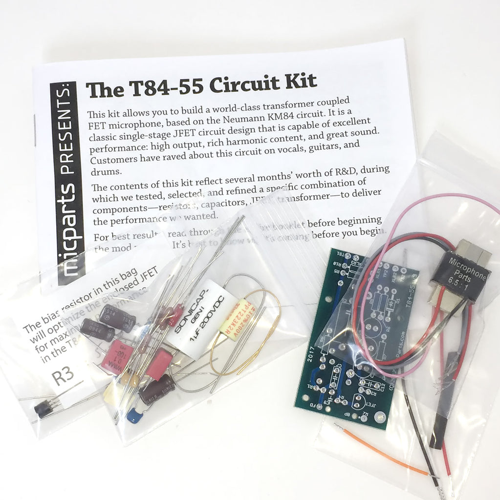
The T84-55 is a single-stage JFET/transformer circuit, based on Neumann's KM84. This circuit kit contains very high-grade components, including a NOS transistor, US-made output capacitors, polypropylene filter caps, and a custom-wound transformer.
This kit is based on our popular T-84 circuit kit, which is the heart of our best-selling transformer microphone kit.M-Audio Luna Capsule Replacement Instructions
The first step (not pictured) is to desolder the two capsule wires from the circuit board. If you are using the stock Luna circuit, photograph the wire positions first, or you will not know how to solder the new capsule's wires later.
 Remove the two screws that connect the mic chassis to the capsule housing assembly. One of the two is indicated by a red arrow in the photo at right. Set these screws aside; they will be needed for re-assembly.
 Remove the two screws indicated in the photo at right. This will free the round capsule housing from its black base. Set these screws aside; they will be needed for re-assembly.
Once the black piece has been moved aside, the two round grille pieces can be lifted or dropped off of the center ring. Take care NOT to touch the diaphragms of the capsule.
 Remove the microphone's original capsule from its saddle by removing the two screws indicated in the photo at right. Set the capsule aside for potential re-use in a different project. (It would work well with the MP-V57 circuit kit.)
 Remove the screw in the center of the white plastic saddle. Retain the saddle for when the Luna capsule is re-used. Save this mounting screw for the next step.
 Install the "supersaddle" included with your RK-47 or RK-12, using the mounting screw from the prior step.
 Mount the new RK-series capsule to the supersaddle. For capsule anatomy and terminology, and mounting instructions, refer to the specific instructions elsewhere on this site:
Locate the hole in the metal ring through which the capsule wires will pass. Position the ring as pictured, with that hole on the right side of the mounting screws. In this position, the capsule is facing down. Locate the diaphragm wire from the top diaphragm (the one facing up) and clip off its bare end. This marks the rear diaphragm wire, and saves time later in the installation process.
Route all 3 capsule wires through the hole in the metal ring.
Reverse the prior steps to re-assemble the capsule/grille housing:
- Place the front and rear grille pieces onto the metal ring.
- Insert the grille assembly into its black base, so that the mounting holes in the base line up with the holes in the ring.
- Screw the base to the ring.
- Thread the capsule wires through the top metal plate of the mic chassis.
- Screw the mic chassis to the black grille base.
- Solder the front diaphragm wire and backplate wire to the circuit, as directed in the T84-55 manual (if you're using the T84-55 circuit) or in the same positions where the original capsule's wires were connected.