Sterling Audio ST55 Mods
The Sterling ST-55 appears to be a slightly less expensive version of the Groove Tubes GT-55; a few capacitors and the JFET have changed, but the core circuit design and transformer appear to be otherwise identical.
The mic has relatively high output, but relatively high noise, and a slightly over-bright voicing that limits the microphone's utility. See further notes on the ST55 capsule below.
We have two modification options for the Sterling ST55:
#1: Capsule Replacement
The capsule in the ST55 is an innovative variation on the common K67 design. It uses a "resonator disk" that is said to "compensate for the 14kHz roll-off" of most large-diaphragm capsule designs. However, this implementation suffers from a significant and harsh-sounding presence peak around 11kHz. Because the mic's circuit is linear, the ST55 capsule sounds too bright and hyped on many sources.
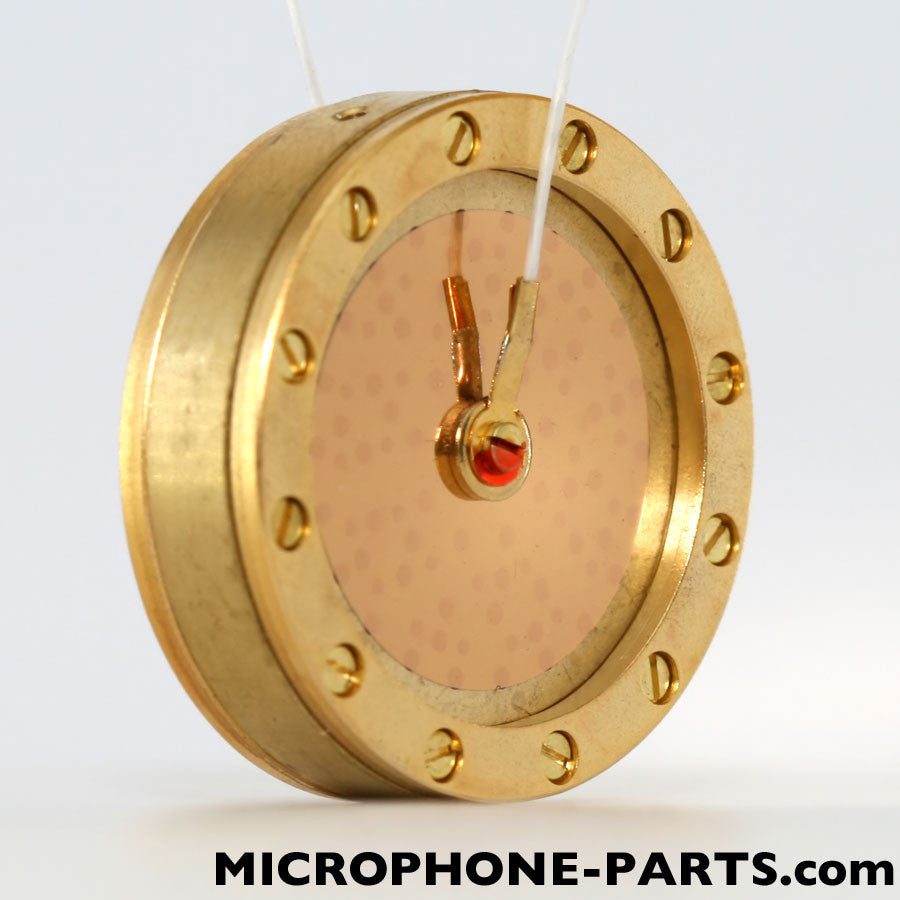 The RK-47 is our favorite upgrade for this mic. It is better suited to the stock circuit than is the ST55's original capsule, and it pairs beautifully with our T84-55 circuit also (see below). The only drawback to the RK-47 is that it is about 1mm too wide to fit through the neck of the ST55 headbasket. See below for specific capsule installation instructions for the ST55.
The RK-12 is an alternative replacement/upgrade capsule for the ST55. It has a broader, lower amplitude presence boost in the high frequencies, giving the a much more balanced sound than does the original ST55 capsule. The RK-12 works equally well with our T84-55 circuit. The drawback to the RK-12 is that, like the RK-47, it is slightly larger in diameter than the neck of the ST55 grille. See notes below on ST55 capsule replacement.
#2: Circuit Upgrade
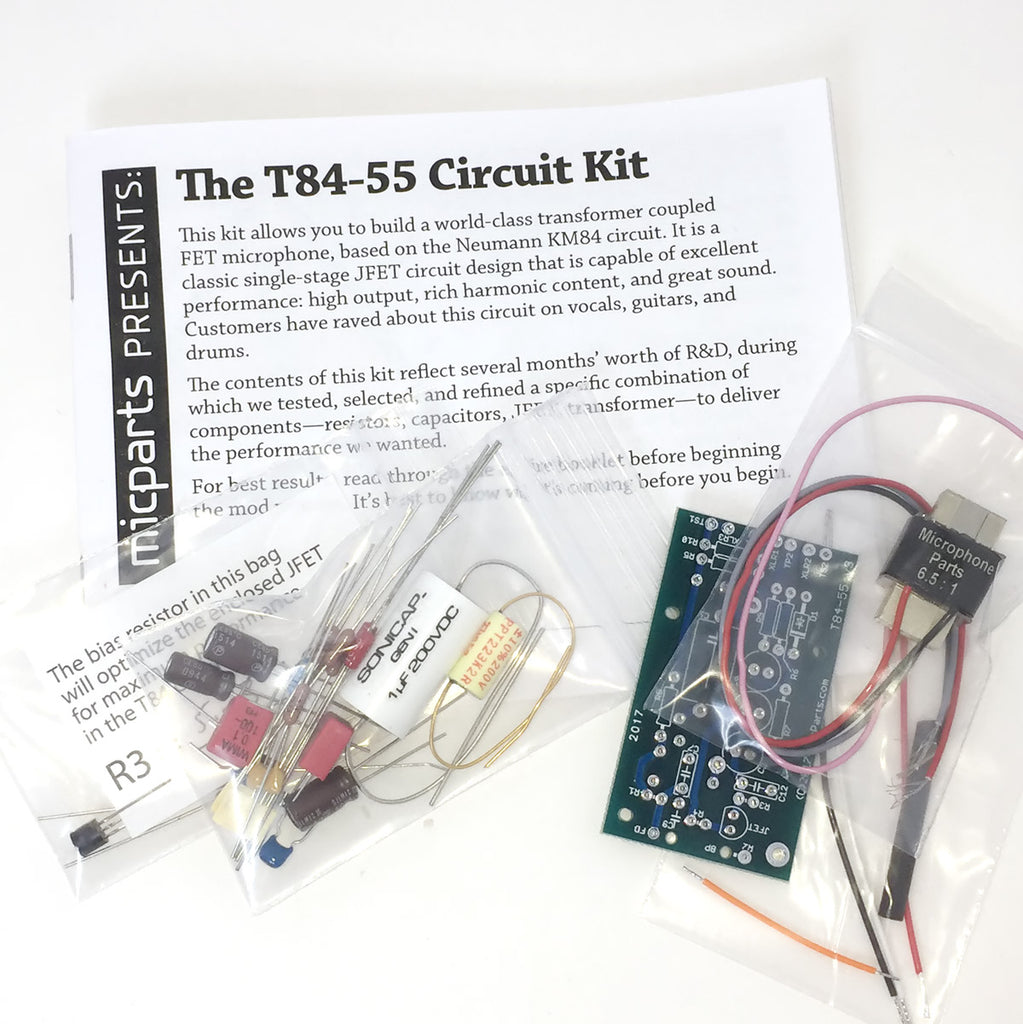
The T84-55 is a single-stage JFET/transformer circuit, based on Neumann's KM84. We build it with very high-grade components, including a NOS transistor, US-made output capacitors, polypropylene filter caps, and a custom-wound transformer.
Sterling Audio ST55 Capsule Replacement Instructions
-
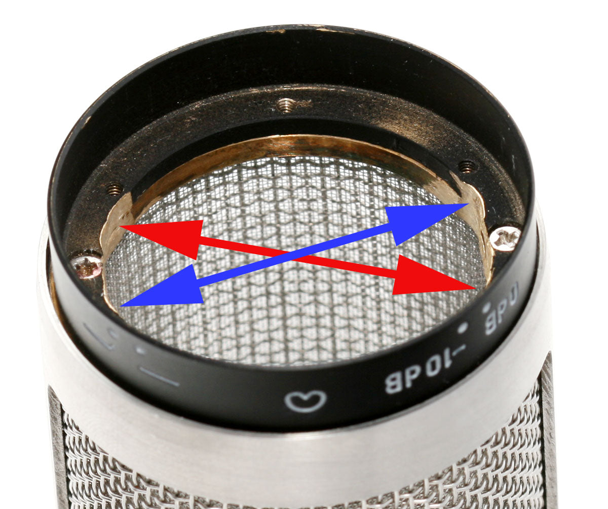 Remove the grille from the mic chassis.
 - Using a metal rasp or Dremel tool, grind away material from the inner ring of the grille as pictured. Do not grind the material at the location of the screws that connect the black ring to the grille; instead, locate the areas indicated by the red OR blue arrows. Remove 0.5—1mm of material from each side, to allow a 34mm capsule to be inserted. Note that dual-backplate capsules like the RK-12 and RK-87 require significantly more grinding than the single-backplate RK-47.
- Knock the grille against a hard surface to remove metal filings and dust from the grille. These could damage the capsule.
- Remove the original ST55 capsule from its saddle. (If necessary, desolder its two wires from the circuit board.)
- Remove the curved plastic saddle from the ST55 mounting post; retain the screw.
- Locate the "supersaddle" (pictured below) included with the RK-12, RK-87, or RK-47 capsule. Carefully sand the two alignment tabs off of the bottom surface of the saddle.
-
 Mount the supersaddle to the ST55 post using the screw retained previously. The photo at right shows the supersaddle on an ST55 (with our T84-55 circuit installed).
 - Mount the new capsule to the supersaddle; see details about which screws and which mounting holes to use on the individual capsule pages linked from here: RK-47, RK-12.
- Mark the wire coming from the diaphragm that faces the front of the microphone. (If your capsule has a rear diahphragm wire, you won't use it. If you can't distinguish the diaphragm wires, or don't know what the "diaphragms" are, see the annotated capsule photos linked from here: RK-47, RK-12.)
- Route all capsule wires through one of the holes in the black plastic domed pedestal, and through the metal plate below the capsule mounting post/pedestal.
- Test-fit the grille. If the capsule does not pass easily through the neck of the grille, return to step 2 to grind a larger slot.
- Once the capsule easily fits into the grille, consider washing the grille under running water to remove all traces of dust and grit. Dry the grille thoroughly.
- Mount the grille to the mic chassis using the screws removed earlier.
- For Cardioid operation, you will connect only 2 wires from the capsule to the circuit board. If your capsule has a rear diaphragm wire, cover its bare end with a piece of tape and tuck the wire (or tape the wire) out of the way. For the T84-55 circuit, follow the instructions in the manual to solder the backplate wire (which, for the RK-47 and RK-12, is blue) to the JFET/1G/terminal joint; then solder the front diaphragm wire to the "FD" solder pad. For the stock ST-55/GT-55 circuit, connect the new capsule's wires to the same locations where the original capsule's wires were soldered.
 Remove the grille from the mic chassis.
 Mount the supersaddle to the ST55 post using the screw retained previously. The photo at right shows the supersaddle on an ST55 (with our T84-55 circuit installed).