Bad Soldering Examples
A customer complained that his 990B/TLMx-49 microphone kit didn't work properly. After several email exchanges, we couldn't locate the problem, so we arranged to get the customer's PCB back for inspection.
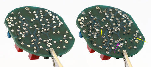
The disaster pictured below is what he sent.

The photo shows the board before and after cleanup. Needless to say, the "before" image is the one on the right.
The three joints indicated by arrows are especially suspect. One has a milky finish. One is covered with flux, such that it is impossible to see if the joint is good. The solder ball on the third doesn't appear to contact the solder pad.
We trimmed the leads, scrubbed the board, reworked all the questionable joints, and cleaned the board again. The result is pictured on the left side of the image.
We did not change any components. But the mic worked fine after the cleanup.
We're including this tip because it illustrates what your finished PCB should (and should not!) look like.

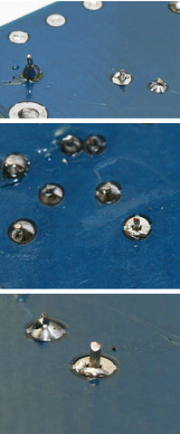
Above is another example: three photos of a failed solder joint. This one passed a continuity test, but didn't form a sufficient connection for the mic to work.
This one could have been found by wiggling every component on the board, or by close visual inspection of the back side of the board.
Have more tips? Send 'em in; we'll publish them here!
