RK-47 Capsule Installation Instructions
K47 Capsule Anatomy
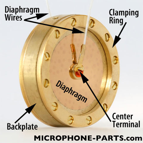
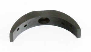
It will be helpful if you know what the parts of the capsule are called. See the image at right.
The backplate is a solid brass disk, measuring approximately 34x8mm.
Screwed to each face is a 34mm diameter clamping ring. The clamping rings hold down the outer edges of the diaphragm, which is a very thin sheet of plastic film, metallized with gold. The diaphragm is also called the membrane.
On the RK-47, each diaphragm is connected to a white wire. During installation, a third wire (usually blue) is screwed into one of the predrilled holes in the edge of the backplate.
Very Frequently Asked Questions
Q: Which side of the capsule is the front diaphragm?
A: Either side can be used as the "front" diaphragm; both sides sound the same.
Q: But the clamping ring on side has a Sharpie mark on it; surely that's the front?!
A: Either side can be used as the "front" diaphragm; both sides sound the same.
Capsule Mounting Hardware
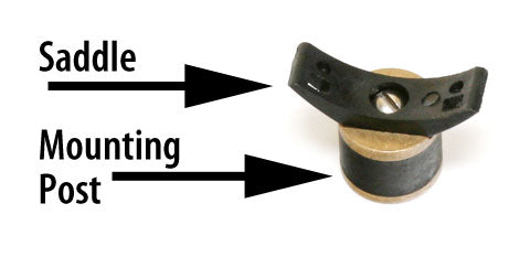
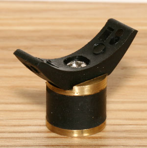
There are two basic styles of capsule mounts found in most microphones. These photos show the names of the various parts.
The saddle is a curved piece of plastic that cradles the capsule. Two screws will attach the capsule to the saddle.
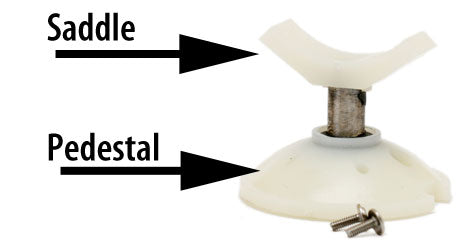
The piece below the saddle is variously called a mounting post or pedestal or domed pedestal. The post or pedestal is screwed to the microphone's chassis, to a flat metal plate called the capsule deck (not pictured).
Never do this!
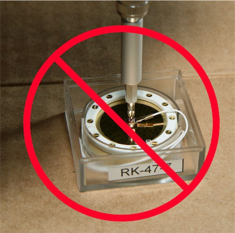
The wires from the new capsule must be soldered to the microphone's circuit. Never unscrew the center terminal wires from the new capsule.

Also, never touch the capsule diaphragms! Hold the capsule by the edge only.
Unbox the new capsule
First, clear your workspace to ensure that you have a clean surface to lay the capsule on.
These capsules are usually wedged into their plastic cases with a short length of transparent plastic tube. This prevents the capsules from rattling around during shipping, but makes it trickier to unbox the capsule. To safely extract the capsule from its cases:
- Remove the case lid.
- Carefully invert the box, being prepared to catch the capsule (by its edges only) if it is loose.
- If the capsule is wedged in its case, rap one edge of the box against the table a few times, open end down (toward the table). The weight of the capsule will push the capsule out of the case partway. You need not slam the case against the table until the capsule flies out completely; rather, tap the case against the table just enough that you can then remove the capsule with your fingers.
Prying the capsule out of the box with a screwdriver is not recommended. There is about a 33% chance that your screwdriver will slip and destroy the capsule's diaphragm.
To keep the capsule safe, set it aside. Cover it with a small piece of cardboard to prevent the exposed diaphragm from becoming contaminated or damaged.
Open the microphone
Most large-diaphragm microphones open by spinning off the threaded base, near the XLR jack. Then, slide off the body sleeve.
 The microphone grille or "headbasket" must be removed. In most cases it is screwed to the microphone chassis using two small machine screws.
In the case of the MXL 1006 pictured here, a second circuit board (which hosts the switch seen in the photo) had to be detached from the chassis first, to allow access to the screws holding the headbasket in place.
The white arrow marks the location of one of the screws holding the headbasket to the chassis.
Be sure to retain all the screws as you disassemble the microphone.
Make notes as you go
 Locate the 2 or 3 wires from the capsule. Take a photo of the microphone to record where these wires attach to the circuit board.
Such a photo is also useful if you accidentally break off another wire or component during handling. It is a critical reference if you end up troubleshooting your installation.
Many Cardioid microphones will have just two wires: one from the front diaphragm (usually from a center terminal, but possibly from the edge or the clamping ring), and a second from the capsule's backplate. (See the top of this page to review what these terms refer to.)
All Multipattern microphones will have three wires: one from each diaphragm (front and rear), and a third from the capsule backplate.
If the leads from the new capsule are soldered to the wrong points on the circuit board, the microphone will no longer function properly. Be sure you have recorded the location of the wires before you remove the original capsule.
Remove the original capsule
Desolder all capsule wires from the circuit board. Be careful to avoid burning nearby components with the soldering iron; we recommend bringing the iron's tip in from the outside edge of the microphone, rather than holding it above the circuit board where heat from the iron could damage a component.
Once the diaphragm wires have been desoldered from the circuit board, unscrew the 2-4 screws holding the capsule to the saddle. Set this capsule aside; later, it can be stored in the plastic case that the new capsule came in.
Install new mount/saddle
If your microphone has a domed pedestal, remove the saddle from the top of the post and install our "supersaddle" in its place. The supersaddle is the black, rigid plastic saddle that came with your capsule.
We recommend putting drop of Loctite™ on the threads of the screw that holds the saddle to the mounting post or pedestal, to prevent the saddle from working loose during a session.
If your microphone has a mounting post, or a 1-piece plastic post/saddle, you will need to choose from among these options:
- Install the short mounting post that came with the RK-47 (pictured at right).
- Or unscrew the saddle from this short mounting post, and install it onto the mic's mounting post.
- Or install the supersaddle onto the mic's mounting post -- although this might require sanding off the alignment tabs from the base of the supersaddle.
If your mic's capsule mount is a rubber or plastic harness, as in the Rode NT1 or Blue Bluebird, you should be able to fit the RK-47 into the harness. This option does not require the use of the RK-47's mounting post or supersaddle.
Saddle Preparation
If you're using the saddle pictured immediately above, whether you've left it on the supplied mounting post as pictured, or transplanted it onto your microphone's existing mounting post, you should test-fit the capsule into the saddle to check for fit.

These saddles are made of a pliable plastic that can contract with temperature variations. If the capsule does not make contact with the center of the saddle, as shown at right, you will need to spread the arms of the saddle by pressing them against a flat surface. This will stretch the arms out, allowing the capsule to sit flush against the saddle. If you skip this step, you will find it difficult to line up the mounting holes in the saddle arms with the holes in the capsule backplate.
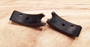
A word of caution -- if you're not paying close attention to this text, and you try to press the supersaddle into a flat surface to spread it, it will snap it two. The supersaddle is made of a rigid plastic and does not need to be reshaped prior to use. (Photo submitted by customer who was not paying attention to these instructions.)
Mount the new capsule
Stand the RK-47 capsule on a flat surface. Hold the microphone, inverted, above it, so that you can look through the mounting holes in the saddle to see the capsule beneath. Rotate the capsule (without touching either diaphragm) until two of the three holes in the backplate line up with the mounting holes in the saddle.
The RK-47 is attached to both saddle types with two screws: one on each arm (or "wing") of the saddle. These screws are included with your capsule.
If you are using the "supersaddle," use the M1.6 screws with small-diameter heads, so that the screw heads fit into the countersunk holes in the saddle.
If you are using the pliable saddle from the short mounting post, use the screws with built-in washers.
(If you need to source more of these screws, what you'll need are M1.6 metric machine screws, with a thread length of approximately 4mm.)
Insert one screw through the saddle. Carefully thread it into the capsule backplate. Tighten the screw until the capsule is just beginning to snug against the saddle.
Then install the second screw through the other side of the saddle.
After both screws have been threaded correctly into the capsule, they can be tightened. Do not overtighten; the threads in the brass backplate could strip, or the screw head could shear off, if you overtighten these screws.
Attach backplate termination wire
If your capsule has three tapped holes in the backplate

Find the blue wire and the short (2mm thread length) M1.6 machine screw that were packed with your capsule. Use the short screw to attach the brass eyelet at one end of the blue wire to the exposed pre-drilled hole in the edge of the backplate of the RK-47.
If you've lost the blue wire, you can use any other wire. Flexible, multi-strand wire of fine gauge (24-28AWG) is best. Form one end into a loop or hook, tin it with solder, and screw that end against the capsule.
If you've lost the tiny screw, any M1.6 metric machine screw will suffice; use wire cutters to clip the threads to a length of approximately 2mm. If the screw won't go into the backplate far enough to hold the blue wire's eyelet firmly against the backplate, back the screw out to trim off some of its length, then re-install. Do not overtighten this screw or its head will break off.
If your capsule has two tapped holes in the backplate

The blue termination wire must be attached to one of the two mounting screws, as pictured at right.
Check capsule alignment
Inspect the capsule alignment to ensure that it faces exactly 0° and 180° with respect to the microphone chassis. In most cases it is possible to gently twist the capsule mount to adjust the capsule position. Do not touch the microphone diaphragms.
Route leads

Be sure you have identified the front of the microphone before routing the capsule's wires.
If the microphone provides only a Cardioid polar pattern, the wire from the rear diaphragm of the new capsule can either be clipped short or wrapped around the post to keep it out of the way. We recommend leaving the wire long, but wrapped out of the way. Just clip the bare end off first, or wrap it in a small piece of tape so that it can't cause shorts or other electrical problems.
Route the diaphragm wires through the capsule mount and chassis as the originals had been. Refer to the photo and notes made earlier.
Replace headbasket
Attach the microphone headbasket to the chassis to protect the new capsule.
Solder capsule wires to circuit
For best results, capsule wires should be trimmed to be as short as possible, leaving only enough slack to reach the circuit board without stressing the wire or joint. Additional wire length leads to an increase in capacitance, which can degrade the signal from the capsule.
If you are experimenting with capsules and expect to be transplanting them across multiple microphones, it is of course best to leave the capsule wires full-length until final decisions about which capsule goes into which mic have been made.

In general, you'll need to solder at least two wires for Cardioid operation: front diaphragm and backplate. For multipattern operation, you would also need to solder the rear diaphragm wire. Refer to the notes made during the removal of the original capsule; the new capsule should be wired identically.
Inspect the solder joints to ensure that they are sound. Research cold solder joints for tips.
Final assembly and testing
Replace the body sleeve and bottom nut. Gently tip the microphone back and forth to listen for rattles. If a screw, washer, or bit of solder is loose inside the microphone, it could cause problems over time, and should be removed immediately.
The microphone's headbasket and body sleeve must be reinstalled prior to audio testing. Without these parts in place, the microphone will hum.
Joint hygiene
After the microphone has passed an audio test, the new solder joints should be cleaned and protected. These high-impedance connections are sensitive to contamination, which can degrade the signal quality and level.
Use 99% pure Isopropyl Alcohol (note: this is not the same thing as 72% or even 90% rubbing alcohol), or a commercial flux cleaner. Never spray aerosol solvents near the capsule. If your solvent is in an aerosol can, spray the end of a cotton swab after moving a safe distance away from the microphone. Then use the swab to scrub the high-impedance solder joints.
Remove all the solder flux and any built-up contamination or grime.
For best long-term results, we recommend covering these joints with "conformal coating." Find specific product recommendations for both flux cleaner and conformal coating here.
Once you are confident the installation work is sound, connect the microphone to your favorite preamp, turn up the gain and enjoy the new microphone!